Lets Motorize a Camera Slider
Free hookup guide and arduino code for this project is available below. This camera slider project came about when one day I decided I wanted to give a more dynamic viewing session. Filming by yourself can be tough, and movement makes things more interesting. I wanted a motorized camera slider. Mostly just so I could let it run while I was doing something. Not only did I want a motorized slider, I wanted to see if I could build one myself. A kind of DIY type camera slider .
I looked online and on YouTube. I found that Max Maker had built a pretty nice DIY motorized camera slider. His system can motorize pretty much any camera slider. I figured I could give it a try. I did end up substituted some of his materials. I either found them less expensive or I found something that would work better for the application.
Being pretty excited to start this project, mostly because it was my first Arduino project. I took the plunge and ordered a 48″ Neewer camera slider. I think at the time when I made the purchase it was on discount on Amazon for $60. The 48″ slider style that I ordered is no longer available, from Neewer, but they do have another style of 48″ slider available that looks super nice.
- Neewer Aluminum Alloy Camera Track Slider
- Nema 17 stepper motor.
- m3 x 10mm cap screws
- Arduino uno r3
- Easy Driver
- A Project Case From Amazon
- A wire kit
- Some standoffs to mount the circuit boards
- DC Power Plug Connector Socket 5.5mm x 2.1mm
- Switches
- Belt and pulleys
- 12V 3A Power Supply
- Plus Various hardware, like m5 bolts, nuts, and
- some washers here and there
Step 1: Mount the Stepper Motor.
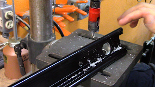
The stepper motor did not come with the 3mm screws to fasten it to the rail, so these had to be ordered as well 🙁 . 4 holes were drilled for the screws, but there was a portion of the rail that was going to cause some binding when tightening the screws to hold the stepper motor on
With the Stepper Drive end complete. It was time to start working on the idler pulley end. This end was not driven and was just going to spin on a 5mm bolt.


Comments
Post a Comment